Yamaha SWP1-8MMF L2 Switch
The SWP1 series L2 switch is ideal for Dante network systems. It features eight etherCON ports, one opticalCON port, and an option slot for one more port as needed.
- etherCON Connectors: 4 front / 4 rear
- opticalCON Connectors: 1 front
- Optional optical module slot: 1 front
- Power consumption: 11W
- Dimensions (WxHxD): 480 x 44 x 362mm (18.9" x 1.7" x 14.2")
- Net Weight: 4.2 kg (9.3 lbs)
Yamaha Switches with Dante Optimization and Network Visibility
Complex network switch setup that was previously better left to an IT technician can now be easily accomplished by anyone. A simple switch setting is all it takes to optimize SWP1 series network switches for Dante operation, and a dedicated computer application called Yamaha LAN Monitor provides “network visibility” for comprehensive monitoring and control.
Yamaha first entered the network device business in 1995, and has grown to hold a significant share of Japan’s small to medium enterprise and SOHO network market. Yamaha gigabit L2 switches that could be linked to Yamaha routers/firewalls were introduced in 2011, with features that significantly reduced the network setup, maintenance, and management workload.
20 years later audio networking has become one of the fastest growing, most highly valued technologies in the live sound and pro audio fields. An expanding range of Dante capable Yamaha products, including the highly regarded CL series digital mixing consoles, continues to lead the way. SWP1 series network switches are a solution the pro audio market has been waiting for, offering an ideal balance of IT and pro audio know-how that only Yamaha can provide.
The Yamaha SWP1 series makes audio network setup, monitoring, and operation easier and more convenient than ever before.
DIP Switch Dante Optimization
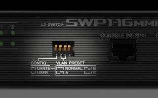
Simple Dante networks are not difficult to set up and operate, but as network complexity grows the switches used need to be optimized for Dante operation in order to achieve maximum stability. Setting up QoS, IGMP Snooping, and other parameters on an intelligent switch can be a complex task, requiring specialized knowledge that is more the domain of IT technicians than audio engineers. The SWP1 series allows a Dante optimized setup to be recalled by simply flipping one DIP switch. No expertise or training is required.
3 Preset VLAN Types
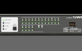
A truly efficient network should be able to handle multiple services simultaneously: Dante communication, StageMix and other smart device functions, computer software that allows digital mixer or power amplifier control, and perhaps more. But the more communication you combine on one network, the greater the chance for interference and problems. The use of virtual VLAN domains to isolate the various types of data is the ideal solution, but this type of setup also requires some IT expertise. The SWP1 series includes three VLAN presets that can be simply selected via a DIP switch. There’s also a USER mode that allows fully customized VLAN setup.

*SWP1-8 ports 9 and 10, SWP1-8MMF port 10, and SWP1-16MMF port 18 become available when the optional MMF-SWP1 is installed.
Network Visibility
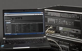
Effective Dante network management hinges on a range of parameters such as network traffic, switch status, and individual Dante device information. The dedicated Yamaha LAN Monitor application provides a comprehensive single-screen view of all necessary parameters when used with SWP1 series switches. We refer to this type of graphical overview as “network visbility.” You can even take a snapshot of the normal network status and set an alarm to warn you if any of the parameters changes, so that problems can be identified and resolved quickly and easily. The Dante Controller application can also be launched from the Yamaha LAN Monitor with a single click, providing a total Dante network solution on a single computer.*The software name of Yamaha Audio Network Monitor has been changed to Yamaha LAN Monitor.
Reliability and Connectivity
etherCON Connectors for Live Sound Reliability
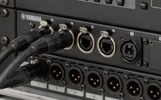
Reliability is essential in live sound applications. Nothing can be allowed to interrupt the show. Conventional network switches usually have RJ45 connectors to match the connectors on the computers to which they will be connected, but the SWP1 series features durable, reliable etherCON connectors that are directly compatible with the etherCON connectors on Yamaha CL/QL series consoles and other Dante capable devices.
Optical Fiber and Network Redundancy Support (option required for redundancy)
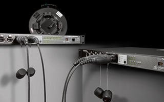
The Yamaha SWP1-8MMF and SWP1-16MMF include multi-mode fiber capable opticalCON connectors. Both models allow transmission over distances of up to 300 meters. The optional MMF-SWP1 optical fiber module can be added to allow two optical fiber cables to be run for redundant connection. Rapid spanning tree protocol (RSTP) is also supported for redundant connections.
EXT DC INPUT for Power Supply Redundancy
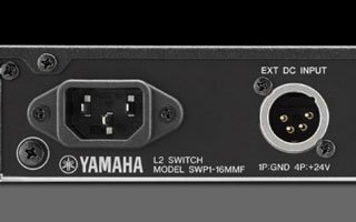
SWP1 series switches include an XLR-4-32 type EXT DC INPUT connector in addition to the standard AC IN connector. +24V DC supplied to the EXT DC INPUT connector provides redundant power that can keep the device running if a problem occurs in the AC supply. For further reliability the AC connector is a locking type (V-Lock) that minimizes the possibility of accidental disconnection.
Network Visibility Advantages
Yamaha SWP1 series network switches were specifically created to give users maximum benefit with the greatest possible setup and operating ease. They allow one-touch Dante optimization plus advanced network visibility while taking full advantage of Dante audio flow management capabilities. Yamaha LAN Monitor software works with the SWP1 series to allow comprehensive monitoring and management of not only any connected SWP1 series switches, but connected Dante devices as well. Yamaha’s original L2MS (Layer 2 Management Service) protocol extends “network visibility” capability to any Dante devices connected to SWP1 series switches.
*The software name of Yamaha Audio Network Monitor has been changed to Yamaha LAN Monitor.
LAN Mapping for a Complete Network Overview
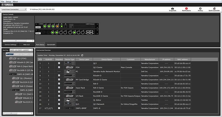
Understanding how multiple switches installed in different locations are connected, plus how network devices are connected to those switches, can be a difficult, time-consuming task. The Yamaha LAN Monitor makes overall network topology clearly visible, giving the user a comprehensive overview of how multiple switches and Dante network devices are interconnected. Simply connect a computer to the nearest SWP1 switch and launch the Yamaha LAN Monitor software.
Port Status and Bandwidth Utilization
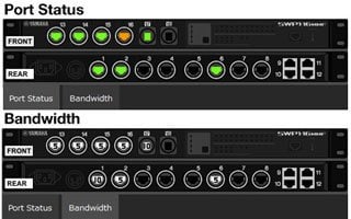
The Yamaha LAN Monitor includes a port status and bandwidth display that clearly shows the connection status of each network switch port, information about the connected devices, the communication speed at each port, and the bandwidth utilization at each port.
Dante Device Info

Device information and monitoring is also available for any Dante devices connected to SWP1 series switches on the network. The ability to monitor primary and secondary port status as well as transmit and receive flow is important to achieving stable, reliable Dante audio communication. This capability lets you keep an eye on the overall “health” of the network.
1-click Dante Controller Launch
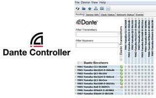
A Dante Controller button at the top of the Yamaha LAN Monitor interface lets you launch the Dante Controller with a single click (the Dante Controller software must be installed on the computer). Seamless switching between the Yamaha LAN Monitor and Dante Controller provides total Dante network control from a single computer.
Snapshot Function Makes Troubleshooting Easy
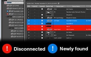
You can take a “snapshot” of the network status when set up as required. The software can then automatically keep track of the settings and alert you to any changes. You could take a snapshot of the network during rehearsal, and then you’d be alerted if a cable is disconnected, if a device is turned off, or if a wrong connection is made prior to the performance, for example.
Enhanced Device ID with Icons, Labels, and Comments
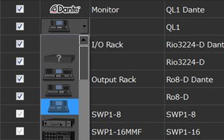
Identifying devices connected to a switch by only their IP or MAC address is a difficult and error-prone approach. Connected Dante devices are identified by a Dante icon as well as a device ID previously set up via the Dante Controller software. You can also enter additional info, such as the location of the device, in the Label and Comment fields.
Detailed Switch Settings and Firmware Updates
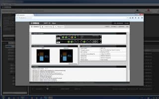
The web GUI for each device can be recalled to provide access to “deep” setting
Specifications
|
|
SWP1-16MMF |
SWP1-8MMF |
SWP1-8 |
|
|---|---|---|---|---|
| Number of LAN ports (1000BASE-T/100BASE-TX/10BASE-T, etherCON connector) | 12 | 8 | 8 | |
| Number of LAN ports (1000BASE-T/100BASE-TX/10BASE-T, RJ-45 connector) | 4 | - | - | |
| Number of SFP ports (1000BASE-SX, opticalCON connector) | 2 (1 optical module is installed as standard) | 2 (1 optical module is installed as standard) | 2 (optical modules are not installed as standard) | |
| Console port | 1 (RJ-45) | 1 (RJ-45) | 1 (RJ-45) | |
| Automatic negotiation | Available | Available | Available | |
| Auto MDI/MDI-X | Available | Available | Available | |
| Switching capacity | 36 Gbit/s | 20 Gbit/s | 20 Gbit/s | |
| Throughput | 27 Mpps | 15 Mpps | 15 Mpps | |
| Maximum number of MAC addresses | 16,384 | 16,384 | 16,384 | |
| Frame buffer | 1024 kB | 1024 kB | 1024 kB | |
| VLAN | Port VLAN, Tag VLAN (IEEE802.1Q), Private VLAN | Port VLAN, Tag VLAN (IEEE802.1Q), Private VLAN | Port VLAN, Tag VLAN (IEEE802.1Q), Private VLAN | |
| Maximum number of VLANs | 256 (VLAN ID 1-4,094) *VLAN ID 1 is the default VLAN ID. | 256 (VLAN ID 1-4,094) *VLAN ID 1 is the default VLAN ID. | 256 (VLAN ID 1-4,094) *VLAN ID 1 is the default VLAN ID. | |
| IP multicast | IGMP Snooping (v1/v2/v3) | IGMP Snooping (v1/v2/v3) | IGMP Snooping (v1/v2/v3) | |
| QoS | 8 egress queues, Policy-based QoS, Remarking (CoS, ToS, DSCP), Scheduling (SP, WRR) | 8 egress queues, Policy-based QoS, Remarking (CoS, ToS, DSCP), Scheduling (SP, WRR) | 8 egress queues, Policy-based QoS, Remarking (CoS, ToS, DSCP), Scheduling (SP, WRR) | |
| Flow control | IEEE802.3x (Full-duplex), back pressure (Half-duplex) | IEEE802.3x (Full-duplex), back pressure (Half-duplex) | IEEE802.3x (Full-duplex), back pressure (Half-duplex) | |
| Support functions | Storm control, HOL blocking prevention, Loop detection, ACL, SNMP agents, Link aggregation (IEEE 802.3ad LACP, Static), Spanning tree (STP*, RSTP*, MSTP), Port mirroring, Port shutdown, Link speed down shift, Packet counter, Power saving mode (IEEE802.3az EEE; Disabled in DANTE mode), DHCP client, Logging, Firmware download via TFTP/HTTP, Config file download via TFTP *STP and RSTP are supported via downward compatibility of MSTP. | Storm control, HOL blocking prevention, Loop detection, ACL, SNMP agents, Link aggregation (IEEE 802.3ad LACP, Static), Spanning tree (STP*, RSTP*, MSTP), Port mirroring, Port shutdown, Link speed down shift, Packet counter, Power saving mode (IEEE802.3az EEE; Disabled in DANTE mode), DHCP client, Logging, Firmware download via TFTP/HTTP, Config file download via TFTP *STP and RSTP are supported via downward compatibility of MSTP. | Storm control, HOL blocking prevention, Loop detection, ACL, SNMP agents, Link aggregation (IEEE 802.3ad LACP, Static), Spanning tree (STP*, RSTP*, MSTP), Port mirroring, Port shutdown, Link speed down shift, Packet counter, Power saving mode (IEEE802.3az EEE; Disabled in DANTE mode), DHCP client, Logging, Firmware download via TFTP/HTTP, Config file download via TFTP *STP and RSTP are supported via downward compatibility of MSTP. | |
| DIP switches | CONFIG, VLAN PRESET | CONFIG, VLAN PRESET | CONFIG, VLAN PRESET | |
| Indicators | Front: POWER, LED MODE×4, PORT×16×2*, SFP×2 *The LED MODE button allows the PORT lamps to be switched between indicating LINK/ACT-SPEED, STATUS, or VLAN. | Front: POWER, LED MODE×4, PORT×8×2*, SFP×2 *The LED MODE button allows the PORT lamps to be switched between indicating LINK/ACT-SPEED, STATUS, or VLAN. | Front: POWER, LED MODE×4, PORT×8×2*, SFP×2 *The LED MODE button allows the PORT lamps to be switched between indicating LINK/ACT-SPEED, STATUS, or VLAN. | |
| Operating temperature | 0 to 40°C | 0 to 40°C | 0 to 40°C | |
| Storage temperature | -20 to 60°C | -20 to 60°C | -20 to 60°C | |
| Power supply (AC IN inlet) | AC100V-240V, 50/60Hz, Internal power supply (no power switch), Power supply inlet: locking type | AC100V-240V, 50/60Hz, Internal power supply (no power switch), Power supply inlet: locking type | AC100V-240V, 50/60Hz, Internal power supply (no power switch), Power supply inlet: locking type | |
| Power supply (EXT DC INPUT inlet) | External power supply requirements: 24VDC±2V, 1A, XLR-4-32 type Connector | External power supply requirements: 24VDC±2V, 1A, XLR-4-32 type Connector | External power supply requirements: 24VDC±2V, 1A, XLR-4-32 type Connector | |
| Maximum power consumption | 16 W, 0.29 A | 11 W, 0.21 A | 11 W, 0.21 A | |
| Heat dissipation | 14.0 kcal/h | 9.5 kcal/h | 9.5 kcal/h | |
| Chassis | Metal case, no fan | Metal case, no fan | Metal case, no fan | |
| Hazardous substances management | RoHS compliant | RoHS compliant | RoHS compliant | |
| Dimensions | W | 480mm | 480mm | 480mm |
| H | 44mm | 44mm | 44mm | |
| D | 362mm | 362mm | 362mm | |
| Weight | 4.6 kg | 4.2 kg | 4.2 kg | |
| Accessories | Power code, Owner's manual | Power code, Owner's manual | Power code, Owner's manual | |
| Options | MMF-SWP1 (Optical expansion unit) | MMF-SWP1 (Optical expansion unit) | MMF-SWP1 (Optical expansion unit) | |
INTERFACE SPECIFICATIONS
| Terminal | Format | Level | Connector |
|---|---|---|---|
| 1-8 *1 1-8, 13-16 *2 *3 | IEEE802.3 | 10BASE-T/100BASE-TX/ 1000BASE-T |
etherCON CAT5e |
| 9-12 *2 *3 | IEEE802.3 | 10BASE-T/100BASE-TX/ 1000BASE-T |
RJ-45 |
| 9, 10 *4 17, 18 *5 *8 | IEEE802.3 | 1000BASE-SX | opticalCON |
| CONSOLE (RS-232C) | - | RS-232C | RJ-45 *6 |
| EXT DC INPUT | - | - | XLR-4-32 type *7 |
*1 SWP1-8MMF, SWP1-8
*2 SWP1-16MMF
*3 These terminals support AutoMDI/MDI-X
*4 The SWP1-8MMF supports the option for port 10, and the SWP1-8 supports the option for both ports 9 and 10
*5 The SWP1-16MMF supports the option for port 18
*6 For the pin assignments, refer to CONNECTOR PIN ASSIGNMENTS
*7 Pin 4=+24VDC, pin 1=GND, pins 2 and 3=N.C.
External power supply requirements: 24VDC±2V, 1A
*8 Conforming cable: GI-type multi-mode fiber cables with a core diameter /cladding diameter of approximately 50 μm/125 μm.
Maximum cable length: 300 m
CONNECTOR PIN ASSIGNMENTS
CONSOLE (RS-232C)
| Pin No. | Signal | 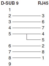 |
|---|---|---|
| 1 | RTS | |
| 2 | DTR | |
| 3 | TxD | |
| 4 | GND | |
| 5 | GND | |
| 6 | RxD | |
| 7 | DSP *9 | |
| 8 | CTS *9 |
*9 These ports are not used on the SWP1.
Dante Mode & VLAN Preset Settings
Common Settings to Dante Mode
- QoS (Quality of Service)
- Enabled
- QoS Trust Mode
- DSCP
- DSCP to Queue (*1)
- DSCP:56 -> 7, DSCP:46 -> 5, DSCP: 8 -> 2, Others -> 0
- EEE (Energy Efficient Ethernet)
- Disabled
Preset Normal
- Ports 1 to 8 (1 to 16)
- Access Port, VLAN 1, LAG Off, STP Off, Loop Detection On
- Ports 9/10 (17/18)
- Access Port, VLAN 1, LAG On (sa1), STP On (*2), Loop Detection Off
- VLAN 1 (for Dante)
- IGMP Snooping: Enabled
- Querier: Enabled (IGMP V3), Query Interval: 30 sec, Fast-Leave: Disabled
- IPv4 Address: DHCP
- IGMP Snooping: Enabled
Preset A
- Ports 1/2, 5/6 (1 to 6, 9/10, 13/14)
- Access Port, VLAN 1, LAG Off, STP Off, Loop Detection On
- Ports 3/4, 7/8 (7/8, 11/12, 15/16)
- Access Port, VLAN 2, LAG Off, STP Off, Loop Detection On
- Ports 9/10 (17/18)
- Trunk Port, VLAN 1/2, LAG On (sa1), STP On (*2), Loop Detection Off
- VLAN 1 (for Dante)
- IGMP Snooping: Enabled
- Querier: Enabled (IGMP V3), Query Interval: 30 sec, Fast-Leave: Disabled
- IPv4 Address: DHCP
- IGMP Snooping: Enabled
- VLAN 2 (for Others)
- IGMP Snooping: Disabled
Preset B
- Ports 1/2, 5 (1 to 6, 9/10, 13)
- Access Port, VLAN 1, LAG Off, STP Off, Loop Detection On
- Ports 3/4, 6 (7/8, 11/12, 14)
- Access Port, VLAN 2, LAG Off, STP Off, Loop Detection On
- Ports 7 to 8 (15 to 16)
- Trunk Port, VLAN 1/2, LAG On (sa1), STP On (*2), Loop Detection Off
- Ports 9 to 10 (17 to 18)
- Trunk Port, VLAN 1/2, LAG On (sa2), STP On (*2), Loop Detection Off
- VLAN 1 (for Dante)
- IGMP Snooping: Enabled
- Querier: Enabled (IGMP V3), Query Interval: 30 sec, Fast-Leave: Disabled
- IPv4 Address: DHCP
- IGMP Snooping: Enabled
- VLAN 2 (for Others)
- IGMP Snooping: Disabled
Preset C
- Ports 1/2, 5/6, 9 (1 to 6, 9/10, 13/14)
- Access Port, VLAN 1, LAG Off, STP Off, Loop Detection On
- Ports 3/4, 7/8, 10 (7/8, 11/12, 15/16)
- Access Port, VLAN 2, LAG Off, STP Off, Loop Detection On
- VLAN 1 (for Dante Primary)
- IGMP Snooping: Enabled
- Querier: Enabled (IGMP V3), Query Interval: 30 sec, Fast-Leave: Disabled
- IPv4 Address: DHCP
- IGMP Snooping: Enabled
- VLAN 2 (for Dante Secondary)
- IGMP Snooping: Enabled
- Querier: Enabled (IGMP V3), Query Interval: 30 sec, Fast-Leave: Disabled
- IGMP Snooping: Enabled
* The port numbers in parentheses refer to those on SWP1-16MMF.
*1 The DSCP to Queue settings are optimized for Dante.
*2 In order to activate Spanning Tree protocol (MSTP), you need to turn off Link Aggregation on the corresponding ports. You can download the Config files with Spanning Tree enabled here.
